Analysis of warping deformation of clinker tiles


Laser scanning
Point cloud
Clinker tiles
Warping deformation
Introduction
The article discusses the modeling of the scanning process of sheet materials (several types of clinker tiles) using 2D laser scanners. During the scanning process, a point cloud is created that represents the geometric surface of the material with a high degree of accuracy. Based on this point cloud, a warpage deformation analysis is performed, which allows determining the degree of deviation of the material from the ideal shape.
Description of scanned samples
The object of analysis is clinker tiles.
Tile:

Step tile:

The requirements for the product are from 0 to 1.5 mm of warpage (the size is determined by a feeler gauge that can enter under the raised corner).

The traditional contact method for quality control in production involves sorting personnel checking 100% of the products on verification plates. This method is labor-intensive. To reduce labor costs, automation using non-contact methods should be considered. Therefore, 2D laser scanners are proposed, allowing non-contact acquisition of a point cloud that reflects the geometry of the product's surface.
Scanning simulation
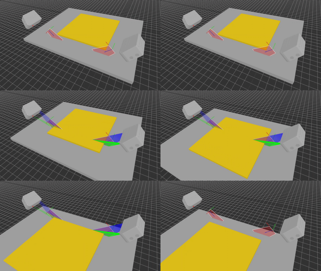
The scanning process is simulated using specialized software developed by me. 3D models of the products were prepared for simulation.
Tile:

One corner is raised to simulate a warping defect:

Step tile:

Similarly, one corner is raised to simulate a defect:

On the conveyor, tiles are placed horizontally. To determine warping deformation, it is necessary to evaluate how much the corners deviate from the base plane.
In this case, it is possible to install several scanners at an angle on both sides to capture the edges and the base surface.

Scanning occurs as the tiles move longitudinally through the scanning area.

Profile at the raised corner:

As a result, a point cloud is created, containing points of the base plane and the object's side areas. The image below shows the gap caused by the defect.

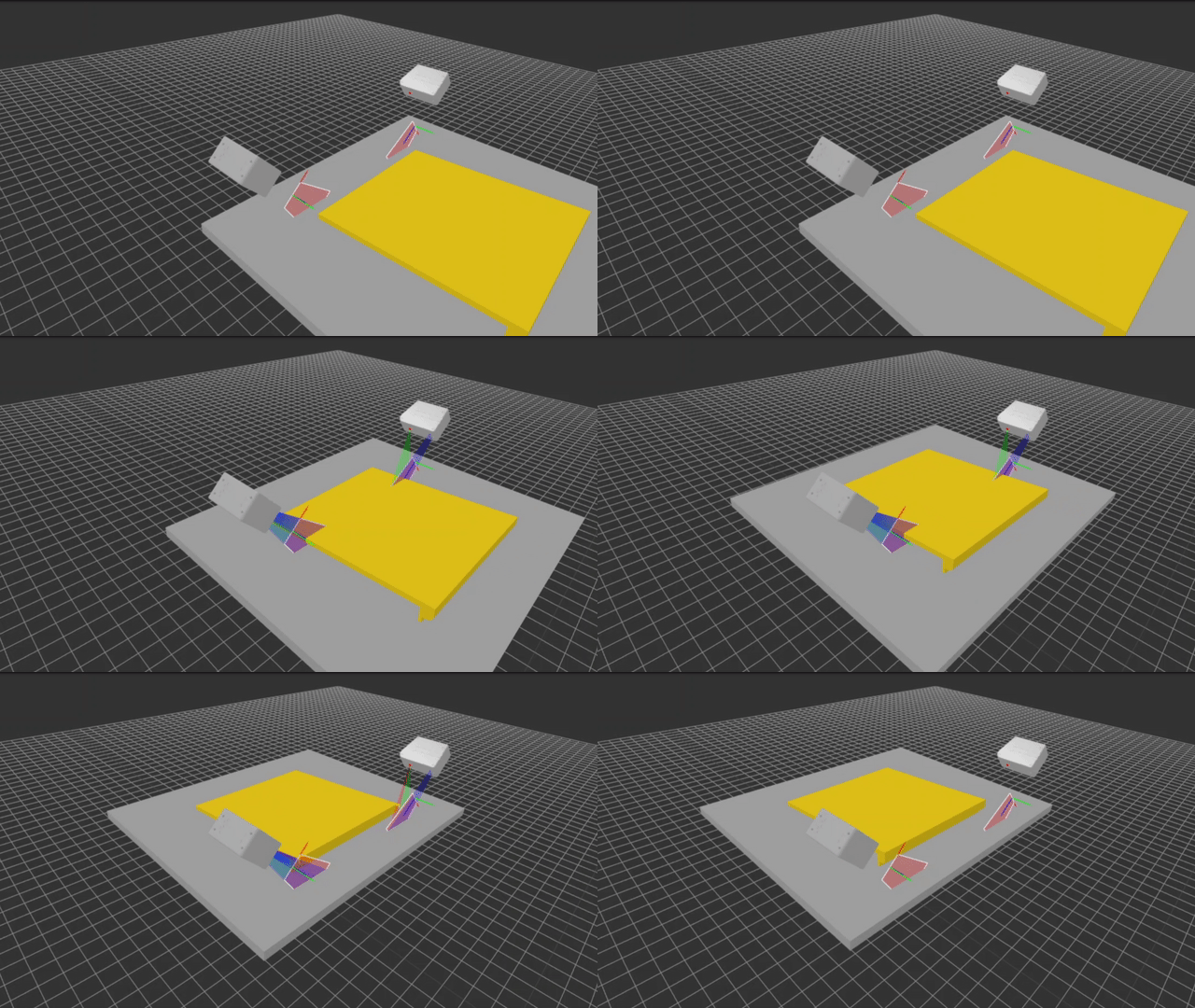
A similar scanner arrangement is used for the step tile:

Scanning process:

Profile at the raised corner:

The resulting point cloud from the scanning process is shown below. A gap caused by the defect (where the tile does not touch the base surface in one corner) is also present.

Based on the obtained point clouds, an example of warpage deformation analysis will be shown.
Warping deformation analysis
To analyze warping, the height of all raised corners needs to be evaluated. The analysis steps are as follows:
1) Separate the point cloud into points representing the base surface and the scanned object.
2) Approximate the base surface points using a plane.
3) Identify the object's dimensions and extract corner areas from the remaining object points.
4) Determine the minimum distance from points in the corner areas to the approximated base plane.
5) Compare the obtained minimum values with the tolerance.
Let's look at the example of a tile. The original point cloud:

The base plane and the tile points are separated. The RANSAC method can be used to detect planes. The lower planes are combined into one common plane.

The corner areas are extracted from the object points. Example for one corner:

Thus, four regions are defined (Section 1–4):

These regions are then extracted from the tile's point cloud.

For each section, the distance from each point to the surface is analyzed, and the minimum value is found. The distances are visualized using a color gradient from blue to red.

Detailed review of each section:
Section 1: Minimum distance = 2.59 mm.

Section 2: Minimum distance = 0.39 mm.

Section 3: Minimum distance = 0.39 mm.

Section 4: Minimum distance = 0.52 mm.

The distances to the base plane for all corners of the tile are shown below. The corner with a distance exceeding the tolerance of 1.5 mm is highlighted.

A similar analysis can be performed for the step tile.
Initial point cloud:

Separation into the base plane and step tile:

Corner areas for analysis:

Extracted corner regions:

Distance visualization to the base plane:

The distances to the base plane for all corners of the step tile are shown below. The corner with a distance exceeding the tolerance of 1.5 mm is highlighted.

Conclusions
1) It is feasible to use 2D laser scanners for analyzing warping in sheet materials.
2) An example using edge scanning was demonstrated via simulation. The scanners were placed at a 45-degree angle to the tile edges during the simulation.
3) During conveyor movement, the tiles must remain stable in all directions within the scanning area. If instability occurs, an alternative setup could involve stopping the conveyor and moving the scanners over the stationary product.
4) The conveyor surface must be even and clean, as its points are included in the analysis.