Measuring brick heights


Laser scanning
Point cloud
Brick
Height measurement
Introduction
This article presents the results of modeling the scanning process of bricks on a pallet to calculate their height. Explanations of the scanning process and examples of the characteristics of the resulting point clouds are provided. An example of analyzing the point cloud to determine the height of each brick is also included.
Description of the Scanned Samples
The subject of analysis is the bricks arranged on a pallet during production. There are small gaps between the bricks. The figure shows a 3D model analog of the scanned objects.

It is necessary to determine the height of each individual brick relative to the surface of the pallet.
Modeling
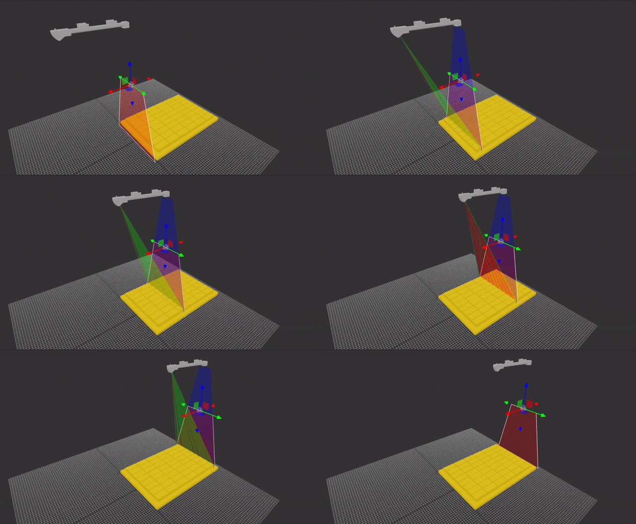
During scanning, the scanner is positioned above the bricks in such a way as to cover all the bricks and the area of the pallet at the edges.

During the scanning process, the scanner must be moved linearly along the pallet with the bricks.

In the central part, the area of the pallet points is visible, as the radiation falls directly into the gap between the bricks, and the vertical sides of the bricks do not obstruct the reflected light from reaching the scanner's sensor. The green lines indicate where the laser beam falls in areas that will be visible to the sensor. The red lines, on the other hand, indicate areas that the scanner's sensor will not see.

At the edges, points of the pallet are almost not registered because either the laser radiation does not reach the area between the bricks or is blocked by the vertical edges of the bricks. This effect is a result of the laser line being expanded into a line from a point source.

As a result, the following point cloud is formed:

The upper surface of the bricks is clearly visible. The surface of the pallet between the bricks is visible in the center but is hardly visible at the edges, as already indicated, due to the radiation being blocked by the vertical edges of the bricks. Additionally, the side surface of the bricks in the extreme area becomes partially visible, the points of which will not be needed for analysis and should be filtered out.

Analyzing Brick Heights from the Point Cloud
The general order of analysis in this case will be as follows:
1) Segmentation of the point cloud into pallet points and brick points;
2) Approximation of the pallet points with a plane;
3) Segmentation of brick points into individual bricks;
4) Approximation of each individual brick's points with a plane;
5) Calculation of the distance between the planes of each brick and the pallet plane.
The initial point cloud:

Points are present on the vertical sides:

These points are not needed for calculations and can be filtered out, for example, using SOR (Statistical Outliers Removal):

Next, we will perform the separation of the point cloud into pallet points and brick surface points. In this case, an effective method will be height-based separation.

Pallet points are approximated using a plane. The arrow indicates the normal vector to the surface.

Brick surface points are segmented into individual bricks:

Then, the points of each brick are approximated with a plane (the arrows indicate the normal vectors to the planes):

After determining all the planes, it is possible to calculate the distance between each brick's plane and the pallet plane. The distance between planes is generally meaningful only in the case of parallel planes. In the process of brick production being considered, the planes may be slightly non-parallel. Therefore, in this case, for calculating the height of the brick, it is advisable to rely on the length of the perpendicular from the center of the brick's plane to the pallet plane. Another option could be to calculate the average distance between the points on the brick's surface and the pallet plane. The figure below shows the direction of the perpendicular from the center. For the extreme brick, the height value is 60.0.

The obtained value corresponds to the height from the model.

The difference in the second decimal place is a result of approximate measurement with a manual tool based on the model.
Conclusion
I hope the approaches to scanning and the methods for calculating brick heights described in the article will help to better understand the laser scanning process and its characteristics. Modeling significantly reduces the time needed to create a prototype. Often, this allows for the development of processing algorithms to begin concurrently with the construction of the movement system, which significantly saves time and costs.