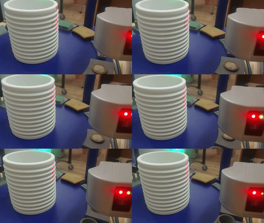
Scanning ceramic cylinders


Laser scanning
Point cloud
Ceramic defects
General
Scanning was performed by rotating the part around its own axis. The scanner is located perpendicular to the surface of the part, the plane of the laser beam passes through the axis of rotation of the part. Scanning was performed for individual areas where the defect was present. A scanner with a range of 10 mm along the Z axis was used.

Scanning
Sample #1
Appearance.

Defect - chipped part of the surface.

The scanning process at the defect site.

Profile at the defect site.

Scan of a surface with a defect, top view.

Scan of a surface with a defect, side view.

The defect is quite visible. The top view shows an uneven area. The side view shows a chip depression.
Sample #2
Appearance.

Defect - a bulge on the surface.

The scanning process at the defect site.

Profile at the defect site.

Scan of a surface with a defect, top view.

Scan of a surface with a defect, side view.

To improve contrast, the area with only the convex part was cut out.
Top view.

Side view.

The defect is quite visible on the cut area. When scanning the entire surface, it is possible to determine the deviation relative to the reference profile. The detection method is described in conclusions.
Sample #3
Appearance.

Defect - a bulge on the surface.

The scanning process at the defect site.

Scan of a surface with a defect, top view.

Scan of a surface with a defect, side view.

The defect is visible in the top view. The contrast is average. It is important that the laser is positioned as perpendicular to the surface as possible. In this case, the surface plane has exactly one color, and the defect is very different. This problem can be solved by correctly painting the surface relative to the axis of rotation of the part
Sample #4
Appearance.

Defect - a bulge on the surface.

The scanning process at the defect site.

Scan of a surface with a defect, top view.

Scan of a surface with a defect, side view.

The defect is clearly visible. Similar to the previous example, it is important that the laser is positioned as perpendicular to the surface as possible.
Conclusion
-
The defects are small in size, so it is necessary to use scanners with a range of 10 mm along the Z axis.
-
Scanning is necessary when the part rotates around its own axis. The scanner must move along the part's rotation axis, since the entire surface does not fit within the range. When scanning, the scanner must be positioned perpendicular to the surface so that the plane of the laser beam passes through the axis of rotation of the part (see the figure for explanation).

-
When scanning defects, it will not be possible to evaluate them quantitatively. It will only be possible to identify the “Defect Present/Absent” criterion and determine the area of the defect.
-
When detecting defects on flat parts, it is possible to color by height relative to the axis of rotation of the part, then the surface is unfolded into an image and uneven areas are determined (for example, by color).
-
To detect wavy parts, it is possible to form a reference profile of the object. Then the deviation from the reference profile is analyzed. After that, a similar scan is constructed based on the deviations from the reference profile and the unevenness of the resulting surface is analyzed.