Scanning of gas turbine engine blades with defect filling


Laser scanning
Point cloud
Turbine engine blades
Defect filling
General
Restoration of a damaged blade can be done by filling and subsequent polishing. This process prevents further damage and extends the life of the engine without the need for replacement parts, making this a cost-effective solution.
The article shows the possible application of laser scanners in the task of scanning defects in gas turbine engine (GTE) blades to search for defects and form a trajectory for filling the defect.
Defect model
A 3D model of a blade has been developed, roughly corresponding to the object of study. This model will serve as a reference for forming the filling surface.

A through cutout has been added at the base to simulate a defect.

Enlarged defect area:

Scanning
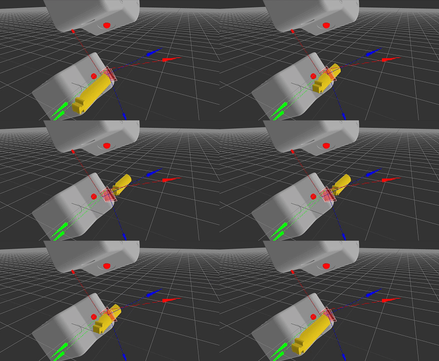
It is recommended to scan the blade from both sides for further comparison with the reference model. It is also possible to scan from one side, but additional conditions for forming the lower boundary of the blade are required. Scanners can be installed on a linear movement system or on a robot. In the case of a robot, the accuracy of forming a common point cloud depends on the accuracy of the robot positioning and on the accuracy of calibration of the robot and scanner in one coordinate system.
The scanners are installed in such a way as to see one of the surfaces of the blades and the side surface of the defect.
Example of scanning the top surface:

Example of scanning the bottom surface:

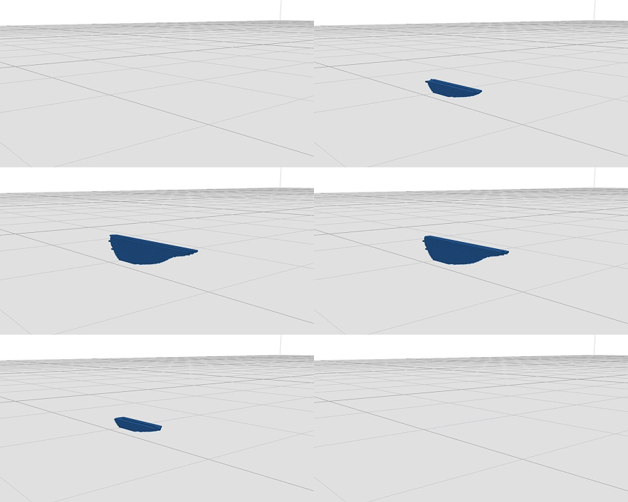
When the scanners or the object move longitudinally, a cloud of points on the surface of the blades is formed, including the defect.

The resulting point cloud:

Point cloud at the defect location:

Post-processing of a point cloud to obtain a fill area
Point cloud at the defect location:

A surface is constructed from this point cloud.

Next, it is necessary to align the scanned surface with the reference 3D model. It is better to determine the transformation matrix based on the alignment of the point cloud with the reference surface, since deviations are possible during the surface formation process due to the approximation of the surface formation and smoothing algorithms.
Aligning a point cloud with a reference 3D model.

Enlarged defect area:

The transformation matrix found during alignment is then used to align the surface with the defect with the reference 3D model.

In this case, unclear boundaries of the defect may appear. For example, on the bottom side.

To solve this problem, various approaches can be used. For example, constructing perpendiculars at the defect location from the upper surface to the intersection with the bottom surface of the reference 3D model. For simplicity, the model with the defect will be slightly upscaled for better display of the defect boundaries (x1.05-x1.07). As a result, a more obvious boundary is formed at the top:

And similarly, a more contrasting border at the bottom:

Next, using surface subtraction, a set of areas is formed, including the area to be filled.

Having removed all areas except the defect area, a surface remains, the volume of which must be filled using the fusion method.

Since the subtracted surface was slightly upscaled, the defect boundary was slightly shifted, which creates a gap.

By upscaling the defect area by a similar amount, the boundary becomes closer to the actual location of the defect.

When using only the top surface and perpendicular methods, surface scaling is not required because the defect boundary is not displaced and no gap is created. However, this method is more difficult to implement.
Formation of the filling trajectory
At the previous stage, the surface of the filling area was obtained, which reflects the deviation of the scanned part from the reference 3D model.
The filling example uses traditional filling approaches used in 3D printers. In this case, filling always occurs from the bottom up. Therefore, it is necessary to orient the filling area at the bottom with the side that is adjacent to the surface of the blade.

After which the filling trajectory is determined based on the required layer thickness and the required step between the filling lines.

Lines of movement of the filling tool head.

After which, the resulting trajectory is aligned back to the model by applying in reverse order all the transformation matrices (inverse matrices) used in the calculations.
Defect filling trajectory, top view:

Defect filling trajectory, bottom view:

Conclusion
-
Laser scanners are suitable for scanning defects of gas turbine engine blades.
-
To form the filling area, it is necessary to construct a cloud of defect points with subsequent subtraction of the defect area from the reference 3D model. If scanning is possible only from one side, it is necessary to supplement the methods for determining the boundaries of the lower surface.
-
The defect filling trajectory can be created from the surface of the filling area using filling algorithms used in 3D printers. This requires proper orientation, as the fill occurs from the bottom up.
-
It is also necessary to determine the direction of the orientation angles of the surfacing tool. The average direction of the blade bending can be taken as the main direction. It is also necessary to take into account the features of the equipment used. Thus, determining the angles of the orientation direction of the tool at each point of the trajectory will be a set of heuristics based on the characteristics of the equipment.